[INSTALLATION · SOUND ART]
A sensor-driven sound installation that treats grief as a retrieval problem
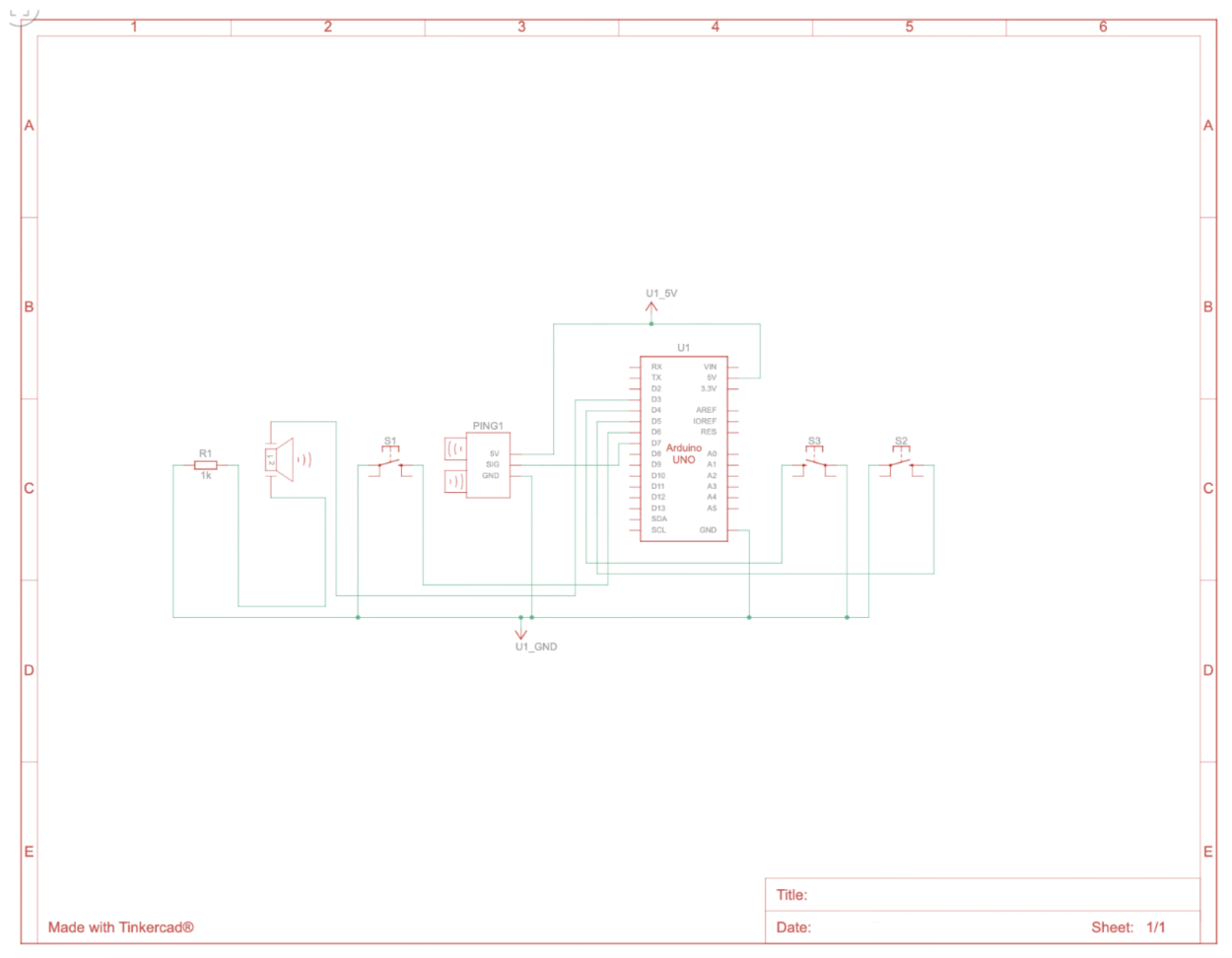
Also titled Random Access Grief, the Memory Distortion Box is a sealed, featureless object built around an Arduino Uno, a photoresistor voltage divider on analog pin A0, and a three-channel Pure Data patch communicating over serial at 9600 baud. The 10-bit ADC reading maps ambient light to playback speed, pitch shift, and reverb depth in real time. When the room darkens past the threshold, the audio begins: slowing, distorting, reversing. When light returns, silence.
Skip to Final Design ↓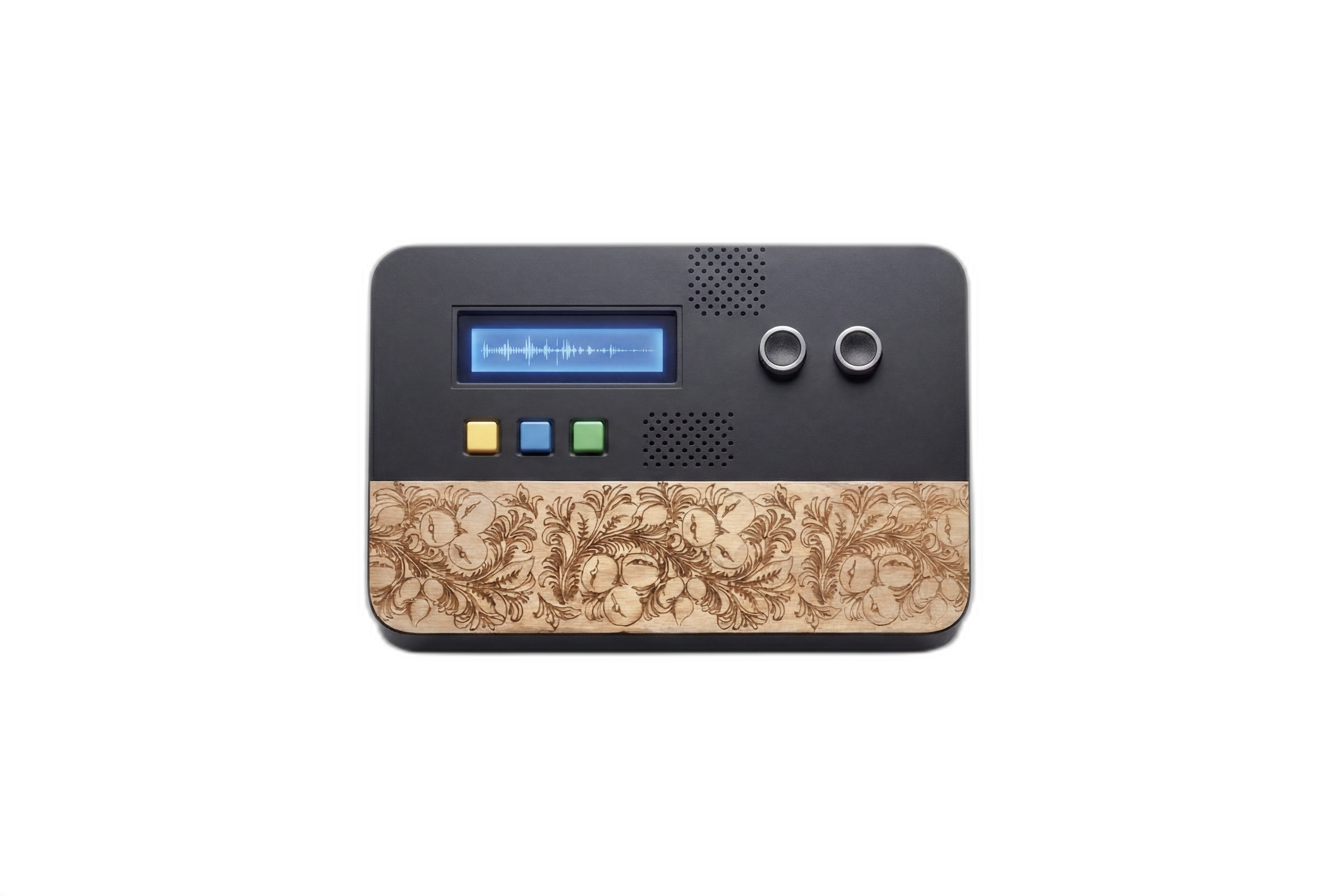
SCOPE
Sound Installation Physical Fabrication Circuit Design DSP Programming
ROLE
Solo. Concept, CAD modelling, laser-cut fabrication, circuit design, and Pure Data DSP programming.
[PROBLEM SPACE]
Grief doesn't arrive when you call it. It arrives when the room gets quiet.
The Memory Distortion Box encodes interaction into the physics of the circuit. The photoresistor on A0 is the only input: no buttons, no screen, no UI. Ambient light keeps the analog read value high and the audio silent. Darkness drops the reading below the threshold (empirically set at 300 out of 1023) and triggers playback. The only way to hear the piece is to physically block the sensor with your hand and wait, which enforces a slowness that most digital experiences do not.
[CONCEPT]
Emotional memory as data corruption. Loss as hardware failure.
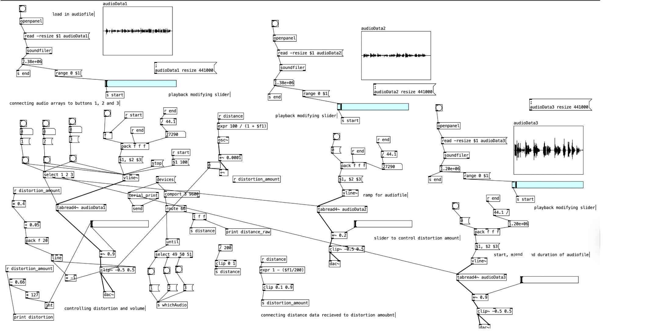
Three audio channels run concurrently in a Pure Data patch, each receiving the same normalised sensor value (0.0 to 1.0) but processing it through different DSP chains. Channel 1 uses [speed~] on a voice recording: playback rate drops linearly with light level and reverses below 0.3. Channel 2 passes a drone oscillator through [pitch~], dropping by up to a tritone in total darkness. Channel 3 drives a granular texture via grain size and density parameters, becoming denser as light falls. The three channels are summed but never tempo-synced, producing a composition that shifts irreproducibly each time the threshold is crossed.
[PROCESS]
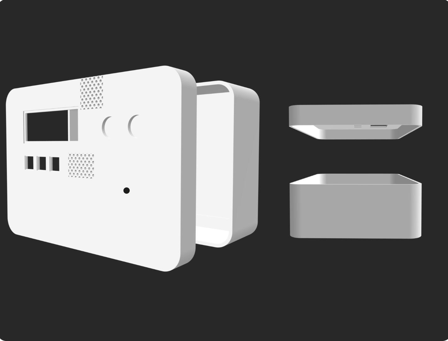
Enclosure
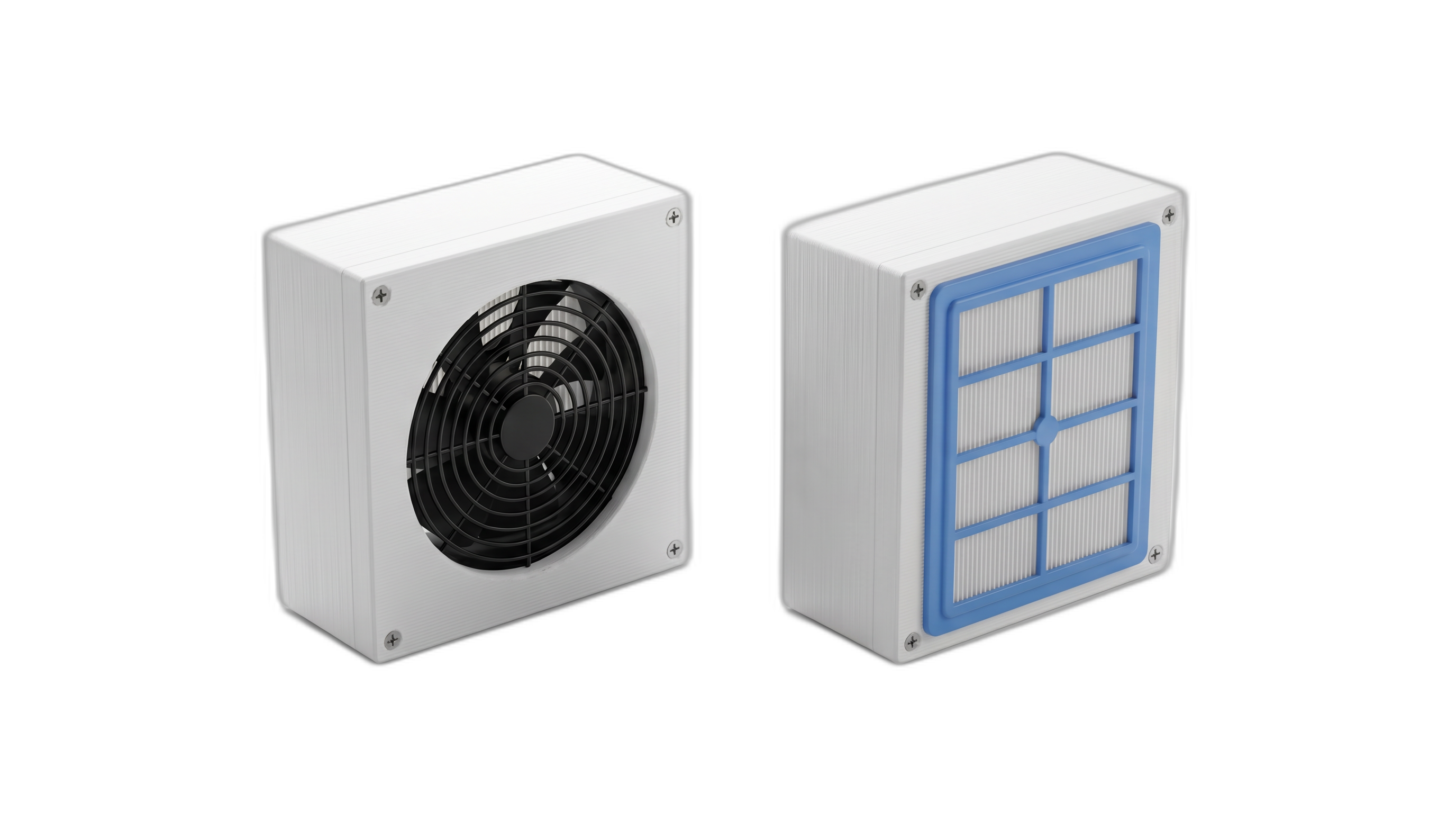
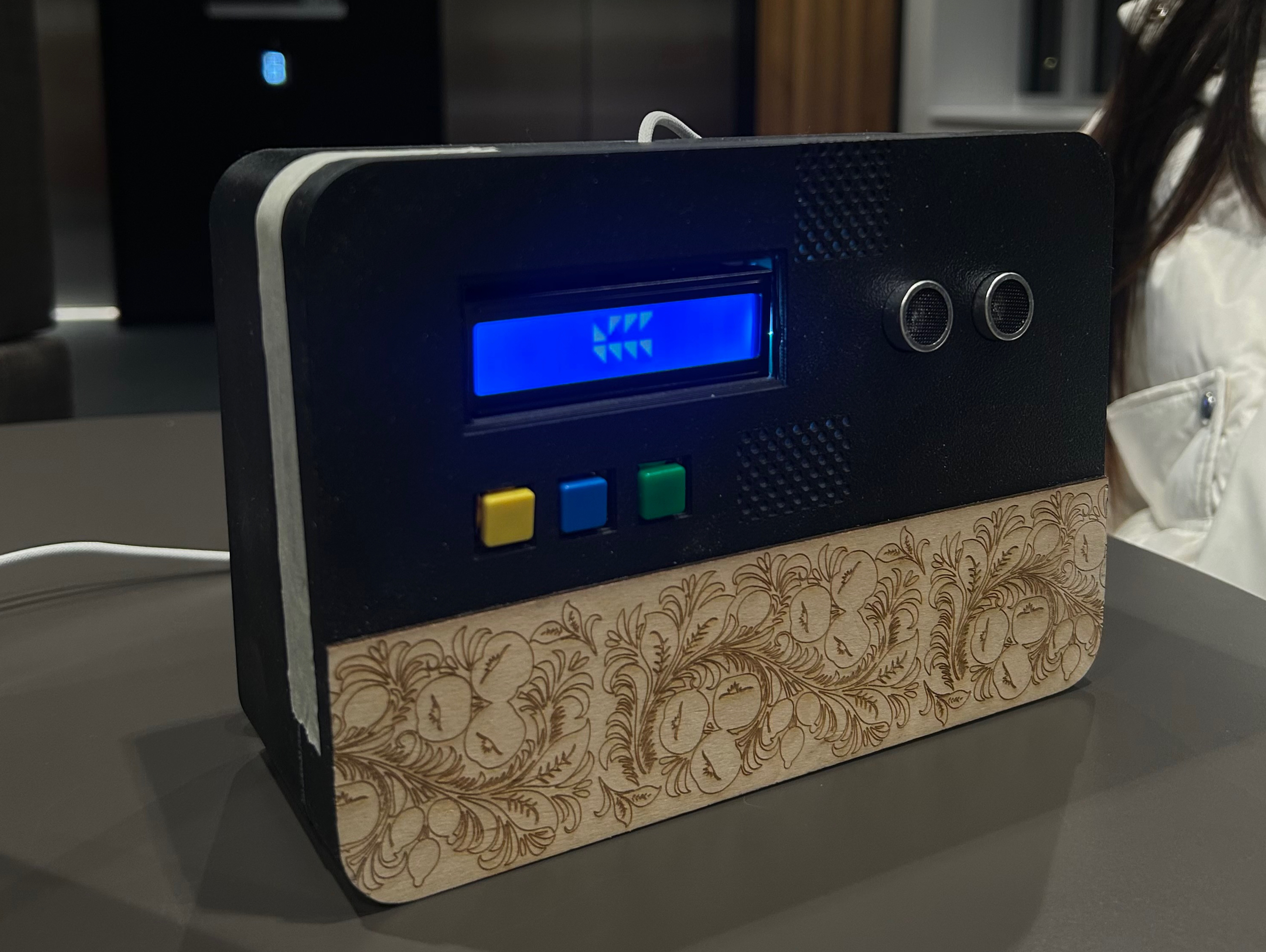
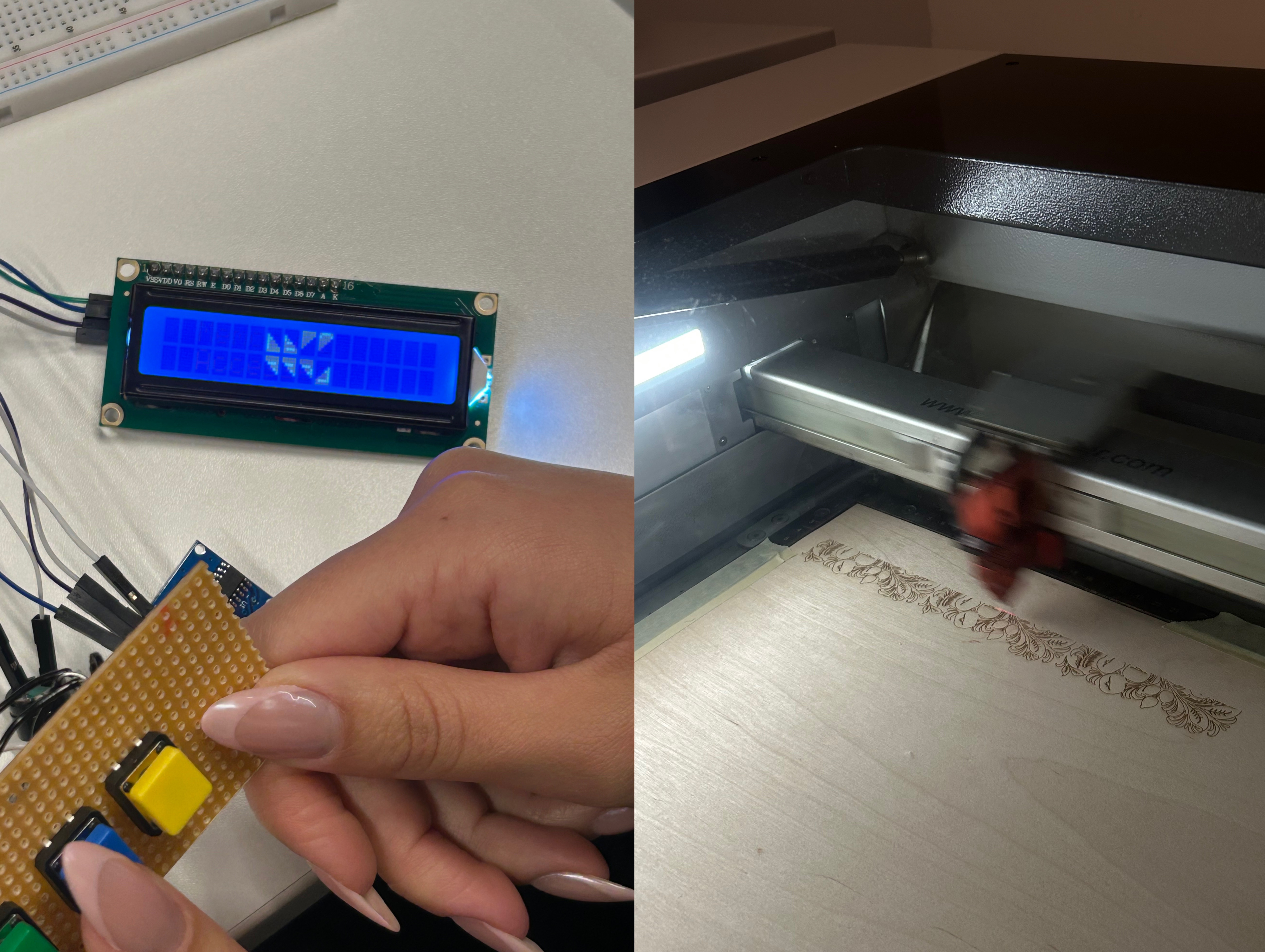
The enclosure was designed in AutoCAD as a 180×120×80mm box with finger-joint edges and kerf compensation set to 0.2mm for the laser cutter. Material: 6mm black MDF, cut on a CO2 laser, assembled with wood glue and internal 3D-printed PLA corner brackets for rigidity. The front face has a 6mm circular aperture for the photoresistor, no label, no indicator LED, no visible seam. The Arduino and breadboard sit on a laser-cut internal shelf; all wiring is routed flush to avoid rattle. The object is deliberately archival in appearance: it should read as a found object, not a prototype.
Circuit and Sensor Logic
The sensor circuit is a standard photoresistor voltage divider: a 10kΩ fixed resistor and an LDR in series between 5V and GND, with the midpoint read on Arduino analog pin A0. The Arduino's 10-bit ADC returns values from 0 (dark) to 1023 (bright). These values are sent over serial at 9600 baud as a single integer per loop iteration. The Pure Data patch receives via [comport] and normalises the reading to a 0.0–1.0 float using [/ 1023]. The threshold (300) was determined empirically during calibration: it corresponds to the ambient light level of a dim gallery room with no directed light on the sensor.
Audio System
The Pure Data patch runs three independent DSP chains fed by the same normalised sensor value. Voice channel: a pre-recorded field recording loaded into [readsf~], routed through a [vd~] variable delay line to simulate speed change. Below a normalised value of 0.3, playback direction inverts via buffer scrubbing. Drone channel: a [osc~] sine oscillator detuned in real time using the sensor value mapped to a pitch range of one tritone (six semitones), processed through a [freeverb~] reverb unit with wet depth also sensor-driven. Granular channel: a custom granular abstraction controls grain size (30 to 300ms), density (1 to 12 grains/sec), and scatter, all inverse-mapped to light level. The three channels sum to a stereo [dac~] output. No tempo sync between channels: the composition is structurally non-repeating.
[FINAL DESIGN]
Memory Distortion Box
Random Access Grief. A box that remembers on its own terms: only in the dark, never twice the same way.
[REFLECTION]
What the audience taught me that the design process did not.
The hand was the right interface all along
Visitors consistently covered the aperture with their palm rather than reducing ambient room light. This collapsed the interaction distance from room-scale to body-scale, which changed what the piece communicated. A v2 would formalise this: replace the LDR with a proximity or capacitive touch sensor recessed into a palm-sized indent, giving the hand a designated place and making the gesture legible without instruction. The circuit change is minimal; the interaction design implication is significant.
Modular patch design is a production requirement, not a preference
The PD patch grew organically during development and became difficult to debug under exhibition conditions. A single misrouted connection could silence all three channels with no obvious visual indicator. A v2 would restructure into named subpatches ([voice-channel], [drone-channel], [granular-channel]) with isolated test modes, a [loadbang]-driven calibration routine, and error state indicators using [print] to console. Maintainability in live installation contexts is a design constraint, not an afterthought.